
OUR PROJECTS

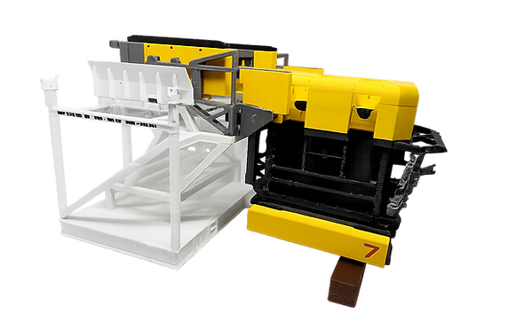
Subsea ROV with Bespoke Drill & Pin Tooling (Capability Demonstrator)
Project Overview
This model was developed as an internal capability demonstrator to evaluate and refine the use of additive manufacturing for complex subsea systems.
The objective was to assess how accurately 3D printing can represent:
-
Congested subsea assemblies
-
Bespoke tooling interfaces
-
Mechanical interaction and access constraints
The model represents a work-class subsea ROV equipped with custom drill and pin tooling, inspired by real-world offshore intervention systems.
Purpose of the Model
The model was produced to:
-
Identify achievable levels of geometric detail
-
Evaluate tolerances for interfacing components
-
Assess assembly methods for multi-part printed models
-
Demonstrate how physical models improve spatial understanding compared to CAD alone
Model Scope & Features
-
Scaled subsea ROV frame and structure
-
Bespoke drill tooling mounted to the vehicle
-
Pin-based tooling interfaces demonstrating alignment and engagement
-
Multi-part construction to replicate realistic assembly sequences
The model was intentionally designed with tight clearances and fine features to push the limits of FDM printing resolution and repeatability.
Manufacturing Approach
-
CAD models were reviewed and simplified to suit scale representation
-
Components were split into logical sub-assemblies to aid print quality and assembly
-
Print orientation and support strategies were selected to preserve critical features
-
Post-processing focused on clean interfaces and dimensional consistency
The model was assembled and inspected to verify fit-up and alignment between tooling components.
Outcomes & Observations
The project successfully demonstrated that:
-
Additive manufacturing is well suited to representing complex subsea tooling at scale
-
Functional relationships between components can be clearly communicated using physical models
-
Assembly-based models provide better engagement during technical discussions than static visuals
-
Printed models are effective tools for identifying potential interface or access issues early
The exercise also informed internal best practices for:
-
Model breakdown strategies
-
Scale selection
-
Feature resolution limits
Confidentiality Note
This model was produced as a non-project-specific capability demonstrator.
It does not represent a live project, client deliverable, or proprietary design.
Relevance to Offshore Projects
Similar models are used on offshore projects to support:
-
Tooling concept development
-
Engineering and constructability reviews
-
Offshore training and procedure walk-throughs
-
Stakeholder communication without exposing sensitive project data
Delivered By
Strategic Modelling Solutions
A trading name of Strategic Subsea Solutions
Developed and delivered by an engineer with over 15 years’ experience in subsea engineering and offshore construction, including work with major offshore contractors such as Subsea7.

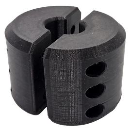
Functional Winch Wire Stopper
Project Overview
This component was developed as a bespoke, function-driven prototype to demonstrate the use of additive manufacturing for mechanical concept development within offshore lifting and winching systems.
The stopper was designed, printed, and presented as an option during a live project to illustrate feasibility, function, and integration within the wider system.
Purpose of the Component
The stopper was designed to:
-
Physically restrain a winch wire at a defined position
-
Prevent unintended wire run-out
-
Provide a clear visual and physical demonstration of the proposed concept
Functional Characteristics
The printed stopper:
-
Interfaces directly with the winch wire
-
Provides positive mechanical engagement
-
Resists sliding under controlled loading
-
Demonstrates load path and contact surfaces clearly
The model enabled stakeholders to physically handle the component and understand its operation without relying solely on drawings or CAD.
Material Selection: PETG
PETG was selected for this prototype due to its balance of strength, toughness, and print reliability.
Key PETG characteristics:
-
Higher impact resistance than PLA
-
Good layer adhesion compared to more brittle materials
-
Moderate flexibility, reducing crack initiation
-
Improved temperature resistance compared to PLA
Outcomes & Observations
This prototype demonstrated that:
-
Additive manufacturing is a powerful tool for rapidly evaluating mechanical concepts
-
Physical prototypes accelerate decision-making during engineering reviews
-
Functional behaviour can be assessed early, reducing later design risk
Relevance to Offshore Projects
Similar additive prototypes are commonly used to support:
-
Engineering option studies
-
Design risk reduction
-
Client and stakeholder engagement
-
Decision-making prior to detailed design or fabrication

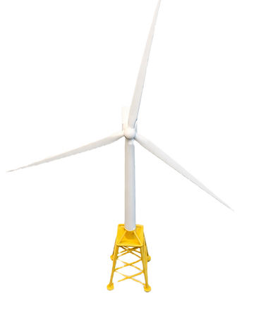
Offshore Wind Turbine Scale Model (Visualisation Demonstrator)
Project Overview
This model was produced using a publicly available offshore wind turbine CAD model to demonstrate the use of additive manufacturing for large-scale offshore infrastructure visualisation.
The objective was to assess how effectively 3D printed models can be used to communicate overall system layout, scale, and spatial relationships for offshore wind projects.
Purpose of the Model
The model was created to:
-
Demonstrate achievable detail for large offshore structures
-
Evaluate visual clarity at different scales
-
Provide a reference example for stakeholder and training discussions
This type of model is representative of those used during:
-
Offshore wind project briefings
-
Early-stage planning discussions
-
Training and induction sessions
Model Scope & Features
-
Full offshore wind turbine structure including:
-
Tower
-
Nacelle
-
Rotor and blades
-
-
Proportions and geometry maintained to preserve visual accuracy
-
Scaled to balance detail with physical handling and robustness
The model focuses on clear visual communication, rather than fine mechanical detail.
Manufacturing Approach
-
Stock CAD model reviewed and prepared for scale printing
-
Geometry simplified where required to ensure print reliability
-
Components printed as separate elements to maintain surface quality
-
Assembly focused on alignment and visual consistency
Outcomes & Observations
This model demonstrated that:
-
Additive manufacturing is well suited to producing clear, repeatable offshore wind models
-
Physical models provide a strong visual reference during discussions with non-specialist stakeholders
-
Even non-functional models significantly improve engagement compared to screen-based visuals
Confidentiality Note
This model is based on publicly available reference geometry and does not represent a specific project or client design.

Tri-Stage 
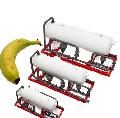
Oil Separator – Multi-Scale Visualisation Study
Project Overview
This project involved the production of three different scaled physical models of the same tri-stage oil separator, using a publicly available reference model.
The objective was to demonstrate how scale selection influences clarity, usability, and understanding when using physical models to support offshore engineering discussions.
To provide an immediately recognisable reference point for scale comparison, a banana was included — a well-established (and unofficial) unit of measure familiar to many engineers.
Purpose of the Model
The models were produced to:
-
Compare how the same system is perceived at different scales
-
Identify optimal scale ranges for offshore review and training use
-
Demonstrate the value of physical scale references versus nominal dimensions
This exercise reflects common offshore challenges, where a model must be:
-
Detailed enough to be useful
-
Large enough to be intuitive
-
Small enough to be practical
Model Scope & Features
-
Identical tri-stage oil separator geometry reproduced at three scales
-
Consistent component layout across all models
-
Visible process flow and major interfaces
-
Mounted on simplified support frames for handling and presentation
The inclusion of three scales allowed direct side-by-side comparison during review.
Manufacturing Approach
-
Publicly available reference geometry reviewed and prepared for printing
-
Identical print and finishing strategies applied across all scales
-
Scale factors selected to represent:
-
Small desk-scale reference
-
Medium hand-held discussion model
-
Large presentation-scale model
-
This ensured differences observed were due to scale, not modelling approach.
Key Observations & Benefits
1. Scale Directly Affects Understanding
Smaller models provide quick context, while larger models enable clearer discussion of interfaces, layout, and flow paths.
2. Physical Size Removes Ambiguity
Even with drawings and dimensions available, stakeholders intuitively grasp proportions faster when presented with a physical object — particularly when accompanied by a universally recognised scale reference.
3. Side-by-Side Comparison Supports Better Decisions
Having multiple scales available allows teams to select the most appropriate model size for:
-
Engineering reviews
-
Training sessions
-
Stakeholder presentations
4. Models Encourage Engagement
Physical models naturally prompt questions, discussion, and interaction in a way that screen-based visuals often do not.
Outcomes
This project demonstrated that producing the same system at multiple scales:
-
Improves clarity during technical discussions
-
Reduces misinterpretation of size and proportion
-
Helps identify the most effective model scale for a given application
It also reinforced the value of simple, intuitive scale references when communicating complex offshore equipment.
Confidentiality Note
This example is based on publicly available reference geometry and does not represent a live project, client design, or proprietary information.
Relevance to Offshore Projects
Multi-scale physical models are particularly useful for:
-
Process equipment reviews
-
Offshore training and inductions
-
Early-stage layout discussions
-
Stakeholder and management briefings